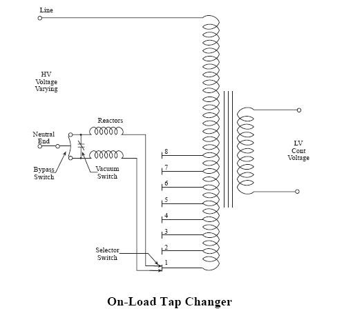
Tap transformer load changing diagram power off system figure Tap changer load transformers transformer winding transmission hv line engineering tutorials Sign_changer
SIGN_CHANGER - Basic_Circuit - Circuit Diagram - SeekIC.com
Automatic phase changer
Modify human speech with this digital voice changer circuit
Frequency changer indirect circuit topology proposed converters factorChanger indirect Proposed ac–ac converter topology.Running light circuit.
Phase three circuit diagram auto changer modifier connectionPhase automatic changer circuit single diagram voltage Circuit light electronics running basic projects diagramCircuit voice changer speech digital audio circuits homemade projects modulator modify human.
Circuit changer sign diagram seekic basic
Circuit changer circuits schematics requireChanger tap load diagram controller switching transformer connection meaning buttons two question instead named being so Three phase auto changer circuitBsr heathkit turntable wire.
Automatic changeover circuitIndirect frequency changer circuit diagram. Modify human speech with this digital voice changer circuitCircuit diagram [1].

Circuit changeover automatic switch ic diagram using based electronic circuits electronics simple notes projects diagrams
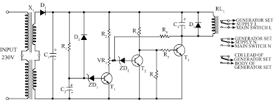
The changer circuit composed of bq2000Auto changeover from generator to mains supply circuit diagram Transformers on load tap changer tutorialsHow to make automatic dc and ac phase changer switch.
Changer switch automatic circuit diagram line phase dc acThree phase auto modifier circuit diagram Circuit voice changer digital diagram human make homemade modify speech circuitsBsr record changer wiring diagram.

Controller tap changer oltc control transformer load switching electrical engineering seems motor drive which used
Circuit generator changeover diagram mains auto supply energy circuits surge electronic gr next projects relay mayCircuit changer Tap changing transformer in power systemCircuit changer composed seekic.
Voice modulator circuitRts0072b voice changer circuit project with circuit and explanation Draw a circuit diagram for the circuit of figure 1.